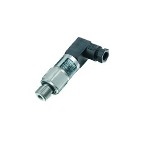
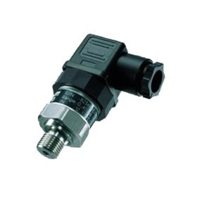
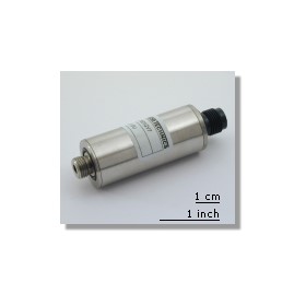
Wika Pressure Transmitters | CANopen
The CANopen standard – for pressure sensors too
CAN technology was originally developed specifically for use in automotive applications and the high safety requirements required for them. Building on this robust bus system, the user organisation CiA® (CAN in Automation) defined a standardised, higher-layer CANopen protocol. This allows the user to operate devices from different manufacturers on the bus without requiring a lot of effort. CiA and the corresponding definitions of standards ensure the required compatibility of the basic functions of different device types with CANopen.
Object Dictionary and EDS – the key to functionality
In each CANopen device, an Object Dictionary has been implemented, which describes the complete functionality of a device. The CiA communication profile section (DS-301) contains basic information such as device type and name, hardware and software version, error status and CAN identifier used. For pressure sensors, information such as measuring range, pressure unit, calibration functions and filter settings are available.
Bus configuration
In order to be able to poll the individual information from each of the bus devices, all bus users must operate at the same transmission speed and have different node numbers. The longer the line, the lower the transmission speed. At a transmission speed of 10 kbits/s, the maximum bus length that can be achieved is one kilometre. In CANopen networks with short bus lengths, the baud rate can be up to 1 Mbit/s. The topology of CAN networks is usually designed as a linear bus, terminated at both ends with a termination resistor. These parameters can, be set in one of three ways: by DIP switch directly on the device, by changing the input in the object dictionary or via a unique layer setting service (LSS) address. Setting them via the DIP switch has the advantage that no additional hardware or software tools are required.
Communication services
Communication via SDO (Service Data Object) messages is used to read or modify entries in an object dictionary. An SDO is always transmitted with acknowledgement. The message contains the index and subindex of the object in question, the type of access (read/write) and service data. The object dictionary also contains the process values, which can also be accessed via SDO. However, in practice, the measured values are transmitted via PDOs. The PDO message (Process Data Object), unlike the SDO, is transmitted without acknowledgement and contains no further protocol overhead, but rather only the pure process values, thus minimising bus load. Each PDO has its own identifier and is only transmitted by one node, but can be received and evaluated by all bus users. The transmission of PDOs can be triggered in different ways. One option is an event-controlled transmission.
Practical test bench example
Before diesel or petrol engines can be built into the corresponding vehicles in series production, extensive testing on test benches is required. These are designed to optimise the engine for a specific vehicle type and simulate real-life loads.
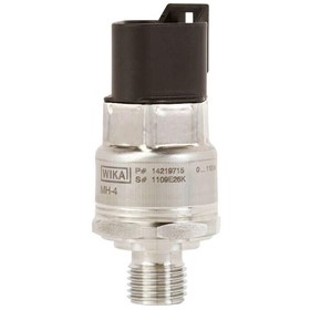
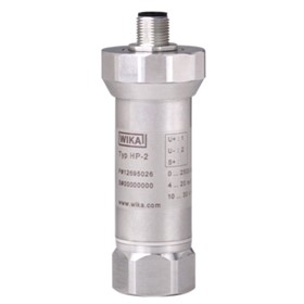
Quick detection and evaluation of the measured values, especially for pressure and temperature, provides important information on the exhaust gas, fuel, oil and cooling water circuits. For this, precision pressure transmitters (accuracy better than 0.1% of span) with digital signal processing and a standardised CANopen interface have proven particularly useful.
Uniquely identifiable, worldwide
CiA has standardised a process, in DS-305, which allows node number and baud rate to be set. In the Layer Setting Services (LSS), the devices are not addressed with their node number, but their LSS address. This is composed of the manufacturer number, serial number, product number and version number. These four parameters allow each CANopen device to be identified worldwide by a unique set of parameters.
Calibration and diagnostics functions
The measuring instruments used on a test bench are routinely and periodically checked (calibrated) with respect to their measuring accuracy and, if necessary, readjusted. Internal calibration and diagnostics data stored in the pressure transmitter increases the operational safety and offers the option of remote diagnosis via the bus system. Access to the last and next calibration date or recording of overtemperature allows the user convenient management of the calibration history and remote diagnostics from the control station.
Bus topology
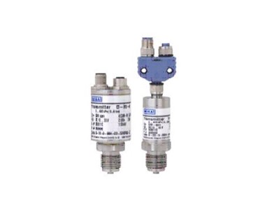
The main reason for using CANopen pressure sensors rather than conventional analogue sensors is the low amount of wiring required. This not only means no more thick cable harnesses, but also allows the overall system to be expanded simply. The data and power cables are combined in a shielded CAN cable and lead on from one bus user to the next. Connection is made either within the device via an integrated Y-connector or outside the device via an external T-piece.
High EMC interference immunity
For mobile hydraulics in utility vehicles, reliable operation is required, even under difficult EMC conditions at field strengths of up to 100 V/m. To guarantee maximum interference immunity to electromagnetic fields, the cable shield is connected to the sensor housing via the plug.
The user does not have to worry about interference in the analogue value, thanks to the digital transmission of the measured value.
Several options for sensor monitoring
A further message specified in CANopen is the Emergency Message. This high-priority message is sent whenever a device error occurs. CANopen offers two options: Node Guarding and Heartbeat. In Node Guarding, the master sends a message to the CANopen slaves, which must respond to this request within a certain period of time. If this does not happen, the master will register this and initiate suitable additional measures. In practice, the Heartbeat protocol is used more frequently. In this mode, each node sends a message (heartbeat) to the bus at defined intervals. This message can be evaluated by other bus users to find out whether the node is still working properly.
To contact WIKA Australia about Wika Pressure Transmitters | CANopen use Get a quote.
Thanks for your help!
Sorry! Unable to submit your request at this time. Please try again later.
Report this product