
Increasingly, however data especially high speed or high channel count data are being transmitted through optical fibres and fibre optic rotary joints, the optical counterparts of electrical sliprings. Electrical slip rings remain indispensable in power transmission on mobile or rotational systems. Sliprings come in a number of varieties based on their brush styles and mechanical structures. Each design fits certain specialised applications. Some are more popular than others. We will discuss the pros and cons of each type in this article.
Brush technologies
A brush is a device that conducts electrical current to the moving member of a slip ring. The moving member is typically a ring shaped conductor. The following brush/contact styles/materials are commonly seen in slip ring designs. There is no single style/material that can solve all the problems. Most manufacturers offer more than one material/style or mixture of them in one device to meet the challenges of the complex needs of different industries.
Pad brush on ring (silver graphite):
Graphite particles are dispersed in a matrix of silver. The silver typically bonds the graphite together, forming continuous high-conductivity paths with a low voltage drop. The graphite burns up in case of arcing. Silver is oxidation-resistant and can maintain clean contact surface during down times. These characteristics allow silver graphite brushes to perform well under high current density conditions.
The brush pad is usually shaped in a small rectangle with the contact surface being cylindrical, providing a perfect interface with the matching ring. Contact pressure comes from the elastic metal leaf or a compression spring the pad is soldered on. The pairing ring material is usually coin silver. The cylindrical contact interface gives this design a large contact surface, making it a good choice for large current applications.
Filament/wire brush on ring (gold on gold):
Another choice is a group of gold alloys forming a mono or multi-filament brush. The matching ring material is also a gold based alloy. A single filament/wire brush has relatively small contact surface with the matching ring. To overcome this, manufacturers often form circular grooves in the rings. That transforms the contact from a single point to an arch, greatly increasing the contact surface. Even so, the current capacity is relatively low (less than a couple of amperes).
This design is extremely low cost to produce and is commonly used on low power and signal transmissions.
When multiple filaments/wires are combined to form a bundled brush, surface contact is greatly increased. Much higher current can be transmitted. Circular grooves not only provide larger contact surface but also prevent the wires from going off track. This structure has been favored by many users in recent years for the combined benefit of low cost and high performance. There were also reports on low wear debris generation and therefore low maintenance.
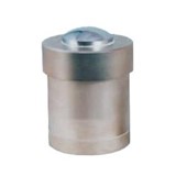
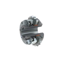
The brushless/roll ring:
Instead of relying on the sliding motion between the ring and the brush, a flexure ring bridges the outer ring and the inner ring. The flexture ring moves very much like a the balls in a ball bearing allowing transmission of electrical power and signal through the rotating interface (rolling contact) with low noise and reduced particle generation. This design greatly reduces the friction and wear. And therefore, they can operate at much higher speed and last much longer. They are called brushless slip rings or roll ring slip rings.
The mercury contact:
In this design, the ring is replaced by liquid mercury. The brush is nothing more than an electrode. There is virtually no friction, no wear and tear on the brush, extremely low noise and low contact resistance (1 milliohm as opposed to 10-20 milliohms in brush/ring type). They offer much longer life span (>1 billion revolution as opposed to several million to tens of million revolutions with sliding sliprings). The main drawback is the toxicity of the material. It requires special handling.
The contactless (Induction):
This is the only design that requires no physical contact between the rotating and stationary members. In this device, inductive components are used to provide a reliable and efficient transfer of electrical power across the contactless rotational interface. The inductive components behave very much like a transformer, but allow relative rotation between the primary and secondary coils. The two coils are coupled by outer and inner cores constructed from layered silicon steel to minimise eddy currents and heat loss. This arrangement achieves reliable and highly efficient transfer of electrical power between the stationary and rotating frames. The slip ring transfers a constant level of electrical power regardless of the position and rotation speed of the rotating coil.
The other benefit of the induction power transfer is that it eliminates arcing, making the device safe in the presence of flammable gases. Like the mercury design there is virtually no friction and no wear and tear between coils. They offer much longer life span than conventional slip rings.
This design is more suitable for power or low frequency signal transmission. It is not ideal for high frequency signals.
The power loss at the contact point for any design is the product of the square of transfer current and the contact resistance. Mercury contact has the lowest contact resistance of all. Other brush materials include carbon graphite and copper graphite.
The drums
A centre rotating shaft holds individual contact rings. Brushes can be pads, filaments, or roll rings. This brush on ring design represents the vast majority of all slip rings on the market. The drum design is scalable, low cost, easy to maintain, and simple to configure to meet different requirements. Many similar or dissimilar rings can be stacked together to achieve very large circuit count.
The basic drum or stack design allows mixing of various voltage and amperage rated circuits to match the actual requirements for each application. Rings are stacked one at a time no matter the number of circuits. This allows manufacture to offer slip ring assemblies matched or customised to the exact requirements of a given application. Custom devices can be built using standard, off-the-shelf ring/brush components. The relative simple structure allows some customers to repair and maintain slip rings on their own rather than sending them back to the manufacture, which typically takes longer to turn around.
One minor drawback of this design is the off centre nature of the brushes. The result is somewhat inflated diameters.
The pancakes
A pair of circular circuit boards, one has concentric ring tracks and the other brushes matching the rings, are placed against each other with a predetermine spacing/pressure. One of the boards is carried by the rotor shaft forming the rotational member of the slip ring.
Unlike a drum, a pancake slip ring has no off-centre component. It usually results in lower weight and smaller volume compare to a drum with the same number of rings. It offers reduced axial length. For high volume applications pancake design can offer very low cost devices given the volume production nature of circuit boards and the low assembly labor cost. Often fancy and creative ring patterns can be realised at little or no additional cost to achieve custom performance. Stacking more than one pair of pancakes in one device in the drum style is also possible making the design scalable. It also provides the manufacturer with flexibility to mix and match different circuit ratings in one device.
Pancake design tents to have greater capacitance and crosstalk, greater brush wear, and higher tendency to collects debris. The concentric nature of the rings produces more wear and tear on the outer most rings. They are not ideal for large current since thickness of plated copper on the board is limited, restricting the current capacity. As wider or multiple traces are added to increase the capacity, a limited number of rings can be placed on one board without overly enlarging the diameter. The overall diameter is also physically constrained to keep the circuit board flat to maintain uniform brushes contact pressure during rotation.
To maintain the advantage of decreased overall height, the pancake slip rings must use brushes with limited length/travel. Manufacturers often resort to a leaf-type springs with contacts directly soldered. They often result in low contact pressure, which makes them more susceptible to weakened contact pressure during vibration, shock, or electrical current passing through the leaves.
Hybrid (electrical/optical) rotary joints
A single strand of single-mode optical fibre has the capacity of carrying digital signals over a trillion bits per second bi-directionally. Modern data protocols such as Ethernet can demand speed up to gigabit per second per channel in both directions, far exceeding the capability of any mentioned slip rings above. As a result, data transmission using fibre along with fibre optic rotary joints (FORJs) has become more and more common. A fibre optic rotary joint in conjunction with an efficient power transfer slip ring, a hybrid slip ring/rotary joint, is a powerful combination in modern mobile and rotational apparatus. Princetel offers numerous off-the-shelf designs that incorporate both slip ring types to serve the market with increasing design complexities.
Water proof
Some slip rings operate in outdoor and harsh environments such as shipboard, oil rigs, and mines. Seals with IP rating 65 or higher is necessary to prevent damages and malfunctions. It is important to provide the environmental details to slip ring vendors at time of ordering. Unfortunately, this is often an ignored factor. All slip rings are not made for outdoor and wet conditions.
Pressure compensation
Remotely operated vehicles (ROVs) operate under water (including sea water. Slip rings installed on those vehicles need to have fluid filling and pressure compensating mechanism to equalise the pressure inside and out. Pressure rating can exceed 690 bar or 10,000 psi (6,850 m deep) for deep ocean conditions. Underwater pressure increases by 101.5 bar or 1,473 psi for each 1,000 m depth. So at the deepest point (Mariana Trench) in the ocean (11,034 m), pressure tops at 1110 bar or 16,250 psi. In other word, a 20,000 psi rated FORJ can allow the vehicle anywhere in the ocean.
The simplest pressure compensator is a short piece of capped elastic tube (external) that is connected to the slip ring body and filled with the same fluid. The fluid volume in the tube is determined by the required pressure. The rough rule of thumb is >10% of the total fluid volume for each 10,000 psi pressure. More sophisticated designs include diaphragms, pistons, bladders, and internal elastic tubes.
Explosion proof
Oil, gas, mining, and some military applications require explosion proof on devices such as slip rings. The requirements are divided into zones, product groups, explosion groups, and temperature classes (see below).
Zones:
Potentially explosive areas are divided into six zones, according to time-related and local probability, that a potentially explosive atmosphere exists. A distinction is made between combustible gases, mists, vapors and combustible dust. Gases, mists and vapors are placed in zones 2, 1 and 0 in increasing order. Zones 22, 21 and 20 are for dust in increasing order.
Product groups:
Groups are divided into group I and group II. Group I consists of mining "underground" and group II deals with prevention of gas and dust explosion protection for all other applications. Product groups determine in which zones the equipment should be installed. Once again there are six categories. Categories 1G, 2G and 3G are classifications for gas explosion protection (G = Gas); to which equipment with 1G for zone 0, 1 and 2, equipment with 2G for zone 1 und 2 and equipment with 3G for zone 2 are suited. Categories 1D, 2D and 3D are classifications for dust explosion protection (D = Dust); to which equipment with 1D for zone 20, 21 and 22, equipment with 2D for zone 21 and 22 and equipment with 3D for zone 22 are suited.
Explosion groups:
Explosion proof equipment for gases, mists and vapors is divided into three explosion groups (in increasing order IIA-IIB-IIC) according to the type of protection being used. The explosion group is a means to measure the gases' ability to ignite.
Temperature classes:
Explosion proof equipment, installed within the Ex area, is divided into 6 temperature classes (T1 to T6 (in increasing order 450, 300, 200, 135, 100, 85 C)). Temperature class is the maximum permissible surface temperature of the equipment, in relation to + 40°C ambient temperature on any surface area, and should not be exceeded at any time. The maximum surface temperature must remain below the ignition temperature of the surrounding medium at all times.
High altitude
High altitude (low pressure) usually does not pose any challenge to most standard slip rings. However, some sealed designs, such as mercury contact, would have pressure ratings. It is a good idea to check with the manufacturer.
High speed
Most slip rings operate at a few hundred rpm. Some applications, such as high speed rotor testing, require rotation speed as high as 100,000 rpm. To achieve that, one has to severely sacrifice the life span of the device. Typical high-speed slip rings can go up to a few thousand rpm. The smaller the diameter, the lower the line speed at the brush/ring contact and therefore the lower the heat generation and wear. Some of the brush blocks in the drum style slip rings may not be symmetrical. So spinning the stator is off the limit at high speed. Even symmetrical brush block designs may not be perfectly balanced for speed higher than a few hundred rpm.
Conclusion
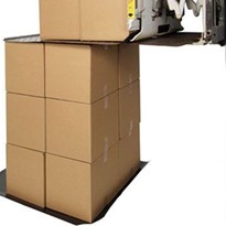
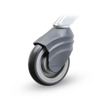
Slip rings are critical components in wind turbines, robotic vehicles, gun turrets, machinery, radars, cameras, security systems, winches, helicopters, mining machines, oil drills, and tethered aerostats. There is a vast array or products on the market to address specific technical challenges. Most are made to orders and a few are standard from off the shelf. Numerous manufacturers with focused technologies and targeted industries can be found in most industrial countries.
The following countries/regions have the largest concentration of slip ring makers: US, UK, Germany, France, Japan, Italy, Scandinavia, China, Spain, and South Africa. LightOptronics Aust. offers both drum and pancake styles from either Princetel third-party makers, and/or Hangzhou Prosper (China). A choice is usually made based on customer's performance requirements, working environments, dimension constraints, budget, quantity, and if required, matching fibre optic rotary joints.
References
1: Contactless magnetic slip rings, http://www.zyn.com/flcfw/fwtproj/Contactl.html
2: Pancakes vs drums: http://www.ien.com/article/slip-ring-technologies/7636
3: Explosion classification: http://www.schischek.com/fire-protection_classification.htm

-205x205.jpg)