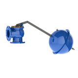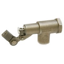
Float switches, in a simple mechanical form, have already been in use for the control of water flows in mills and fields for centuries and today still represent the most frequently used technology. A hollow body (float), due to its low density and buoyancy, lifts or drops with the rising and, respectively, falling level of the liquid. If one uses this movement via a mechanical lever, e.g. as a simple flap control for an irrigation channel, one has implemented a mechanical float switch.
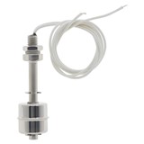
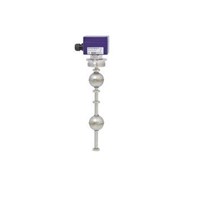
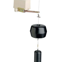
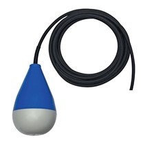
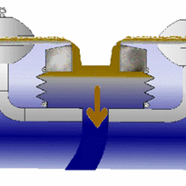
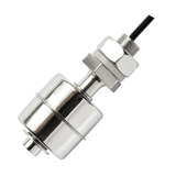
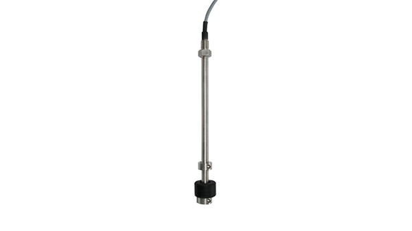
Modern float switches, of course, are used for switching an electric circuit and feature a clearly more sophisticated design. In its simplest form, a float switch consists of a hollow float body with a built-in magnet, a guide tube to guide the float, adjusting collars to limit the travel of the float on the tube and a reed contact located on its inside (see figure).
How does the float switch function?
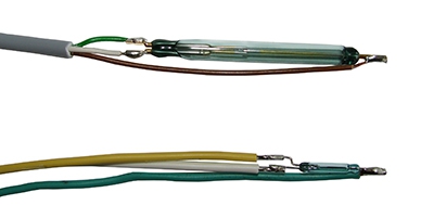
Reed contacts (see figure) of a float switch feature contact leaves within the hermetically sealed glass body, which move together or apart from each other when a magnetic field is applied. In the case of a float switch with a reed contact with a normally open function, on applying a magnetic field, the leaves are brought into contact. When the contact between the leaves is made, a current can flow via the closed leaves and a switching signal will be detected.
In the case of a float switch with normally closed switching function, the contact or circuit is interrupted on applying a magnetic field. If one selects a change-over contact, the glass capsule will contain three contact leaves, with which, at all times, a normally closed and a normally open contact are simultaneously made in every operating state.
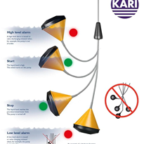
Since the contact leaves are under a mechanical preload, a magnetic field must be applied in order that the contact leaves close or open in order to generate the desired switching signal (monostability). The adjusting collars fitted by the manufacturer serve as a limitation for the float body in the correct position, to ensure / maintain the desired switching signal on reaching the defined filling level.
How does one specify a float switch?
The following parameters should be defined:
- Number of switch contacts / switching outputs
- Position and function of each switching output
- Guide tube length
- Electrical connection (e.g. PVC cable outlet)
- Process connection
- Material (stainless steel, plastic, …)
Note
As a leading provider of float-based measurement technology solutions, WIKA has a wide range of variants to meet all your application-specific requirements. Please contact us for more information.