
The 4..20 mA current loop with HART interface remains the industry standard for transducers. A fieldbus interface with device integration capability and scriptable configurability offers an inexpensive retrofit for these devices for operation with Foundation FIELDBUS and PROFIBUS PA.
It’s now been 25 years since work started on developing fieldbuses for the specific requirements of process automation. Foundation Fieldbus H1 and PROFIBUS PA use a ‘Manchester Bus-Powered’ (MBP) physical layer compliant with IEC61158-2 Type 1. As with the analogue 4..20 mA current loop, this permits a remote feed to the devices and the development of intrinsically safe devices for potentially explosive atmospheres.
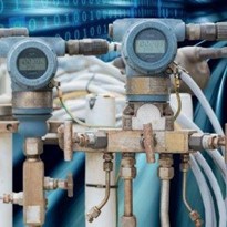
Although the digital communication protocols include a powerful feature set and offer many advantages in practice, fieldbuses are used in only a small part of production systems. There are many reasons for this lack of acceptance. The control systems use only the process values from digital field devices, and not their diagnostic and parameterization options. Or the ‘control in the field’ models that utilize intelligent field devices are not supported by the control systems. Users therefore see virtually no benefits in using fieldbuses, and also face complex challenges when commissioning, troubleshooting and replacing devices. In the future, however, Industrie 4.0 and derived concepts such as the NAMUR Open Architecture will be focusing on the extensive data that digital field devices can supply for diagnostics and asset management. It is a fact that at least three-quarters of all transducers and positioners being installed today are still equipped with the trusty old 4..20 mA current loop. For this reason, the standard models of field devices typically have an analogue interface, which is usually supplemented with a HART interface for parameter setting. Manufacturer-specific interfaces for parameterization and diagnostics are also often included.
Despite this, new (and often very large-scale) production systems are also designed around fieldbus, which means device makers must ensure they also offer products for this segment. The analogue power interface and HART modem must also be replaced with a digital fieldbus interface. This requires development work for both software and hardware.
Fieldbus interface
A specialized fieldbus controller is required for the generation and reception of the Manchester-coded transmission signal, and also to maintain correct bus timings. For signal modulation (which is implemented by modifying the internal power draw) as well as decoupling the energy supplied from the bus, another IC – termed a ‘Medium Attachment Unit’ – is also required. For simple, low-cost sensors, the fieldbus interface is connected to the microcontroller on the device – although this does require the porting of the highly complex fieldbus protocol software to the device architecture. A simpler approach is either to develop a fieldbus interface with its own microcontroller featuring optimal adaptation to the protocol stack or to source the fieldbus interface complete with firmware from a specialist provider. This also guarantees freedom from interference between the device application and fieldbus communication, as both components feature time-sensitive functions.
Application integration
Developing the hardware is only the first step in the process, however. Foundation Fieldbus and PROFIBUS PA specify not only the fieldbus communication behavior but also many properties of the application that runs on the field devices. Both fieldbuses also make use of very similar block models which distinguish between three categories of blocks:
• Function blocks (generic) – implemented identically on each device, these blocks provide input/output functions for the process quantities, plus certain control and processing functions such as PID controllers or totalizers. An analog input block, which provides the measurement value, therefore has a fixed set of parameters, regardless of whether it is a simple temperature sensor or a complex radar level meter.
• Transducer blocks are used to represent the parameters, which depend on the measurement principle or control/make available a field device’s specific function. For each input/output function block, at least one transducer block is provided to generate (for sensors) or process (for actuators) the process value. In addition, transducer blocks can also be used to access diagnostic functions or utilize the local operating interface, for example.
• Lastly, each field device has exactly one resource block (Foundation Fieldbus) or physical block (PROFIBUS PA), which enables access to certain items of device data such as manufacturer ID, serial number, version level, etc.
The software side of fieldbus integration therefore involves mapping device functions to the function block model so that the device presents
itself to the fieldbus as interoperable and compliant with specifications. For a parameter from a function block to be read via the fieldbus, the
corresponding value must be generated by the device application. Conversely, a fieldbus write operation must pass the new value to the
application. Dependencies between the parameters must also be accounted for. If a temperature’s physical unit is converted from Kelvin to Fahrenheit, for example, then only the parameter in the transducer block that represents this physical unit is written to on the fieldbus side. In the device, however, this conversion means that all of the quantities using this unit must be recalculated – including the process value, the upper/lower limit to the measurement range, alarm limits, and so on. Since field devices often have hundreds of parameters, this represents a significant workload for the development of a device-internal application that integrates the device function with the protocol software. This also requires close collaboration between the stack developer and the device developer in cases where the expertise for communications and device architecture is not concentrated in the hands of one person.
As a result, the budget for a fieldbus integration project can quickly run into a six-digit amount, while the time required to achieve completion is typically between 6 and 12 months. While this kind of effort may be acceptable for major manufacturers, this approach is not attractive to smaller manufacturers who sell only small volumes of fieldbus equipment.
Simple integration without programming effort
For this customer segment, Softing Industrial Automation has developed an integration model consisting of a hardware module and a development tool, which enables the straightforward retrofitting of HART and Modbus devices for Foundation Fieldbus and PROFIBUS PA without any programming.
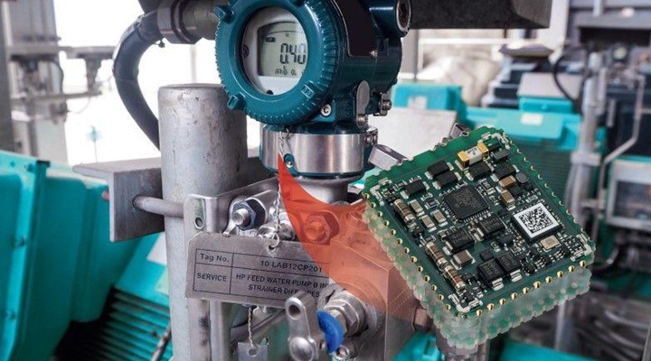
A ‘commModule MBP’ module measuring just 32 mm × 39 mm provides all of the h/w and s/w functions needed for fieldbus connectivity.
With its single-sided assembly and edge metallization, the intrinsically safe module (ATEX- and IECEx-certified) can be mounted on a circuit board using an automated assembly line. For the device manufacturer, hardware development effort merely involves providing the space and the connection interface on the circuit board itself. The supply voltage on the fieldbus ranges from 9 V to 32 V. The module’s current draw can be configured in software from 10 mA to 26 mA.
This energy taken from the fieldbus is used to supply the connected field device with 3.15 V or 6.2 V and up to 16 mA, so that a maximum
of 90 mW (approx.) is available. A programming/debug interface enables the download of firmware and configuration data to the device.
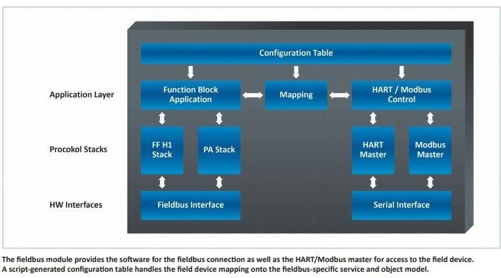
Communication with the HART or Modbus device is handled by a serial interface. I/O signals are also available. For fieldbus communication, both a Foundation Fieldbus stack and a PROFIBUS-PA stack are provided. The protocol is selected using a hardware line. For communication with the field device, a HART stack and a Modbus master stack are available. In the device, this means that the FSK modem (for HART) or the RS-485 interface (for Modbus) is bypassed. This saves energy while allowing higher serial transfer speeds of up to 115.2 kbit/s. A new feature here is a configuration application on the module, which feeds the fieldbus objects with real-time data from the field device via HART command or Modbus access, or transfers data to the field device.
Device mapping
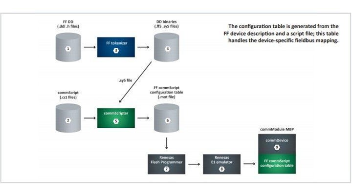
With its Universal Commands and Common Practice Commands, HART defines a set of standardized functions. Access to other data is manufacturer-specific, using device specific commands. With Modbus, while certain address areas are assigned to basic functions like read or write, no further semantics are defined as standard. Accordingly, the mapping of the function block parameters to the data in the field device means that, for each individual object, it is necessary to define the HART command or Modbus register that will be used to read or write the object value, and how the device response (HART) or the register content (Modbus) is to be interpreted. This assignment is made in a script for each device. Due to the similarity between the Foundation Fieldbus and PROFIBUS PA models, an identical script can be used for both protocols – only a few items of information in the script are protocol-specific. The script is then checked for proper use of syntax with the ‘commScripter’ script interpreter and compiled into a binary configuration table. This table is stored in the fieldbus module’s flash memory storage, where it handles the mapping of fieldbus services onto the HART/Modbus commands. If a HART device needs to be upgraded for FF use, for example, then the following workflow applies.
The device developer describes the device from a fieldbus perspective in the obligatory device description ? and also creates a script file ?
that specifies how the function blocks and their parameters can be read or written to via HART commands. The tokenizer ?, a DD compiler
distributed by the FieldComm Group, compiles the device description into a binary format (.ff5) and also creates a symbol file (.sy5) ?.
This file is required by the commScripter tool ? in order to generate the configuration table ?. This table is now present in a standardized
format (.mot), and is transferred to the fieldbus interface board with suitable tools (in this example: a flash programmer tool and an emulator from Renesas).
The commModule is exported as a neutral version with all named stacks as well as the mapping application, and mounted on a board during
production of the field device as a single-chip solution. This board must provide a connector for module programming, so that the mapping table can be downloaded to the module – either in a production step, or at a later point in time as a device- or project-specific configuration step. This combination of commModule and commScripter therefore enables the low-effort, cost-effective, and flexible integration of Foundation Fieldbus and PROFIBUS PA into existing field devices and devices still in development.